
By Cleon Regensburger
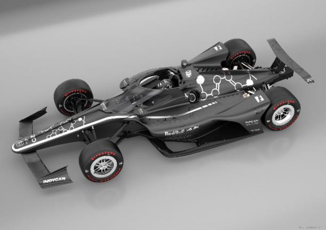
Back in 2020, IndyCar’s new Aeroscreen was under close scrutiny as it made its race debut, but the device has been extensively tested already before to even make it to its deployment on racetracks around the US. Since it was introduced back then to the Formula-Series, it had a big impact on the overall drivers’ safety.
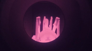
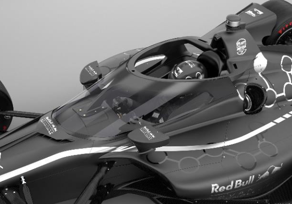
The remarkable system is made up of a 3D-printed titanium framework engineered by Red Bull Advanced Technologies (RBAT) and manufactured by the Austrian-based company Pankl. The screen itself is developed by PPG with the aim of protecting the racing drivers against small part intrusion into the cockpit.
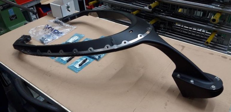
However, the tube-like structure on which the polycarbonate windshield is mounted, can definitely be seen as a work of art. Weighing below 30lbs (~13.6kg), the titanium frame is made from five additively-manufactured parts welded together.
Several manufacturing methods were evaluated in the early stages of the development cycle. The initial design was made for titanium casting, but looking at the tight schedule to the first race in 2020, using this method was clearly not an option. Hence, 3D printing became the most feasible option. Being a relatively young manufacturing technology that firstly has to prove itself for such safety-critical applications, it was clear that a company with experience in the high-performance sector needed to be addressed with this task. Pankl Racing Systems is a well-known tier-1 supplier in the high-performance, racing and aerospace industry that established an Additive Manufacturing (AM) Competence Centre with a high number of dedicated specialists focusing on the development and production of additively manufactured high-performance parts and systems. This was the perfect fit and therefore, the Austrian company became the manufacturing partner in this project. The whole Aeroscreen assembly consists of four sub-systems: Carbon fibre frame bonded onto the chassis; Top frame (which is the 3D printed structure); Screen; Aero fairing. IndyCar is the first racing series in the world using the advanced technology Additive Manufacturing to produce a safety-critical system in the size of an Aeroscreen. Hence, the interest in how the technology stands up to scrutiny has been extensive.
When it comes to structural integrity, it has already exceeded expectations in the laboratory-testing phase where it was loaded with a force equivalent of 34,000lbs (~15.5t). Further, the ballistic screen was tested by a 17.3lbs (~7.8kg) object striking it at 220mph (~354km/h). The screen also had to prove its performance mounted on a car and was therefore intensively tested on the racetrack, first in October 2019 at the Indianapolis Motor Speedway, but also on several occasions until its debut in an official race in February 2020. Since then, it had a substantial impact on the safety of IndyCar racing as Will Power (2014 and 2022 IndyCar champion) points out: “I’m so happy that we have it. It’s really a huge step in safety!”
Metal Additive Manufacturing
Compared to conventional machining methods, where material is usually removed from a solid block to create the final shape, additive manufacturing is doing the opposite. In this process, the raw (powder) material – in the case of the Aeroscreen top frame titanium powder was used – is added and fused together successively to create a part.
To do so, the 3D-CAD-file that has to be printed, is sliced into a large number of very thin and flat (2D) layers that represent the cross-sections of the part in their respective z-height, dependent on a previously defined layer-thickness. In the powder-bed process used in this case, the part is then built up layer-wise by using an energy source such as a laser (or in some cases also an electron beam) that melts up the powder and transforms it into a solid structure. After one layer is finished by the laser, a recoating system puts fresh powder on top and the loop starts again, so the part is growing layer by layer in z-axis as the third dimension, which is the reason why it is also called 3D printing.
Since AM is utilizing a totally different way to produce parts than the traditional, well- established manufacturing methods, it is not subject to constraints and limits of these. This offers several great benefits.
As already indicated, physical parts can be 3D-printed directly from digital data without any tooling. Furthermore, the parts have nearly any geometrical limitations, which leads to new possibilities for designers and companies. Hence, AM primarily influences the development process of products in the way that the principle is design freedom and not the “design to manufacture” approach anymore. This implies the opportunity to enhance component properties through complex geometries, internal structures and cavities (as used in the design of the top frame).
 Also, it enables advanced part characteristics and integrated functions like cooling channels or lattices. Additionally, the part count of complex assemblies can be reduced, as several parts can be consolidated into one when additively manufactured. So, instead of having many parts joined together to form an assembly that is capable of carrying out the assigned task, AM can manufacture the whole assembly as a single piece. This not only reduces assembly work, manufacturing costs and time, but also increases reliabilities.
The aforementioned extended design possibilities compared to the conventional production methods can additionally help to reduce the weight of a part, which in turn means that the limits of part performance and lightweighting can be shifted significantly. This includes special design techniques such as topology optimization (numerical design method) and biomimicry.
Another big advantage is the potentially significant reduction in lead time compared to conventional machining, casting or forging processes. Furthermore, development costs can also be reduced. Changes in prototype design do not affect the subsequent manufacturing process and tool-less production allows machines to be adapted more quickly to market needs and enables on-demand manufacturing. So, prototypes and functional parts can be produced with this significant reduction in lead time, which is of major importance in demanding markets such as the racing sector. There, it usually helps a lot to run additional development loops and to test several different technical options in parallel on the dyno or on track as the development schedules are usually very tight.
But of course, there are not solely advantages using AM – some challenges are inherent. For example, minimum wall thickness, removability of the powder in the internal cavities and minimum surface overhang angles are critical parameters in 3D-printing of metal components.
When processing metals in AM, also warping is a challenge that needs to be addressed. Preventing warping effects and distortion is mainly done by using support structures. Such supports link the part to the base plate, acting as anchors which are usually removed after stress relieving/heat treatment. Further, they act as heat sinks to conduct the excess heat away from the part. The necessary support structures are simply printed together with the part itself in one shot. These supports are so-called sacrificial volume, that has to be removed from the parts after completion of the print job (manually or through machining). Which results in higher costs due to added machine runtime and material needed. Therefore, it is a compromise between process stability, part distortion and costs when setting up an AM- buildjob.
To support this task, Pankl makes extensive use of process simulation. Part distortion can be reduced through simulation, by pre-distorting part geometries (or so-called distortion compensation). Still, the tolerances of fully machined parts can hardly be met and surface roughness is also a characteristic that needs to be considered. But if additional machining of functional surfaces with tight tolerances is required for the final part, the effort in terms of CAM programming and machining time starting with the printed raw part is, on complex or topology optimized parts, most of the time quite small compared to produce a fully machined component.
To turn attention towards costs, AM usually can have an advantage on smaller production volumes and especially on huge but thin-walled and complex, intricate parts as the complexity in printing is “for free”. For high volume mass production of simple non-performance components, it has to be mentioned, that conventional machining or casting is usually the more cost-effective solution.
Additive manufacturing plays off its strengths
As previously highlighted, there have been two main reasons for the decision to go for AM on the top frame of the Aeroscreen: timeline and mass reduction. The overall project time schedule was very tight and starting from the decision to have an Aeroscreen in IndyCar in 2020, the target was to get the first systems available at the first track test: a two-car test at Indianapolis Motor Speedway on October 2nd, 2019 with Will Power and Scott Dixon (see picture below).
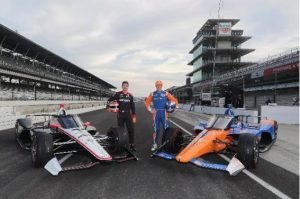
The target was also to have extra parts available on time for 2020 season’s homologation, which was planned for October as well. Thinking about the fact, that the design process started just some months before in April 2019, it was clear that with any other manufacturing option this timeline could not have been realized.
In fact, the timeframe was set so tight that for the initial test of the Aeroscreen, the first top frame prototype had to be flown in the hand luggage of a Pankl employee from Austria to the US.
The second reason was mass reduction compared to the initially intended casting option, which helped to keep the impact on the overall car weight and the centre of gravity as small as possible.
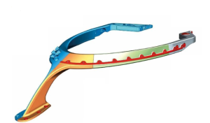
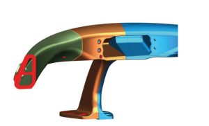
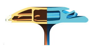
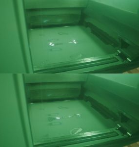
All in all, the 3D printed version of the top frame weighs below 30lbs (~13.6kg) and is about 3lbs (~1.4kg) lighter than the initial cast design.
On the left side a section through the AM version is shown. In this section the internal cavities of the hollow design are visible, while on the right side the heavier casting version can be seen:
Pankl’s Additive Manufacturing Competence Center
Since its beginnings more than 30 years ago, Pankl has become a well-known supplier in the top-level motorsports, high performance and aerospace industry. For all these markets Pankl is not only known as a supplier, but also as a system partner for complex projects.
Together with its industrial partners EOS and voestalpine Boehler Edelstahl, Pankl has established an EN9100 certified additive manufacturing competence centre in Austria where they can cover the complete value chain of AM: starting from powder production, printing, heat treatment including hot isostatic pressing (HIP) as well as the final machining of printed raw parts. This holistic approach is seen as crucial for Pankl to improve AM part quality and performance substantially, as there is a stronger interaction of the single aspects in the process chain inherent than in other manufacturing technologies.
Using AM for producing the top frame of the Aeroscreen is unique as the AM technology is relatively young compared to well-known conventional production processes and as there is only a small number of companies worldwide that are able to print titanium parts of such size. This project definitely demonstrates the innovation spirit within the racing segment in general, but especially from the Indy Racing League (IRL) as it is the first safety critical part developed like this for the market.
As indicated above Pankl’s understanding to cover the complete process chain from cradle to grave is the basis to establish AM for such high-performance driven and safety critical parts. Also, for the top frame of the Aeroscreen this approach can be seen as the key enabler.
Well-founded co-operation guarantees success
Pankl’s main partners in this project were RBAT (Red Bull Advanced Technologies), who were responsible for the design and the validation of the product and the Italian company Vsystem who was in charge of the welding and fabrication of the single printed components into the final one-piece top frame assembly.
Each of the individual process steps needed special care and absolute expertise as most of it had to be developed or refined in and during the project.
On top of that, a lot of work had to be done parallel – so, a very clear communication and careful project planning between all the different members was the key to success.
In the first phase of the project, RBAT has designed already a cast titanium version of the top frame, as this was the intended manufacturing process initially. Due to the tight schedule, a switch to AM was necessary and with the input of Pankl, RBAT redesigned it partly to make it better printable.
As already mentioned, there are some points to consider when designing for AM in order to get the most out of a design and to push it to its limits. A clever design is not only structurally on an optimum, but also takes the manufacturability into account. Generally, it can be said that in AM the design and production of a component goes hand in hand. For example, a slight adaption on the parts orientation on the printing platform can have a significant impact in the overall process and potentially make a change of the parts design necessary. It is a key element in metal AM to understand the strong dependence between part design and its potential impact on the print process to exploit all benefits this technology is offering.
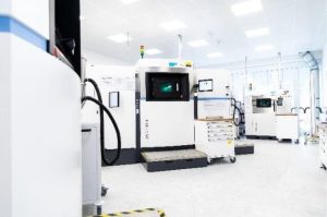
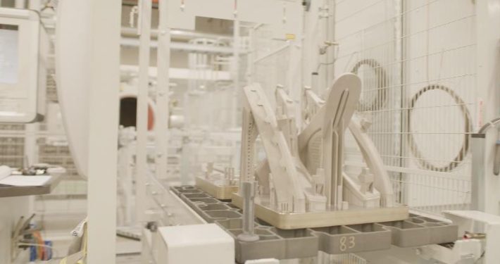
An additional challenge in this project was the size of the top frame. Due to the overall dimensions it was not possible to print it in one piece – even on the biggest additive manufacturing systems available on the market. Consequently, Pankl had to cut the top frame into five single pieces for an efficient printing on the EOS M400-4. This state of the art AM production system is a multi-laser machine with 400x400x400mm in build space. Four 400W lasers are working in parallel during the manufacturing process to significantly improve the production speed compared to conventional single laser systems. Machine productivity is the main driver for the costs of the parts in general.
After the final part design was frozen, the blank design was created for printing. The difference between the blank and the final part is that the blank has additional material added for final machining of the functional areas and clamping straps.
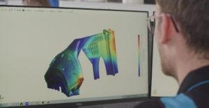
Good design of these geometric features for clamping the parts during the final milling process is important. On the one hand, they need to be strong enough to hold the parts accurately during the milling and subsequent welding process, and on the other hand, they need to be as small as possible because the extra material increases the printing time and material consumption – and therefore the costs. Once the raw part design, the orientation on the platform and the support structures were done, Pankl could start to perform several loops of printing process simulations to investigate internal stresses, temperature distribution and deformations during the print job and to optimize the key parameters and buildjob-setup to reach the quality and dimensional tolerance targets and good process stability. The results of these simulations are used to optimize the support structures and to pre-deform the CAD to compensate of the part caused by thermally induced internal stresses during the print job.
This state-of-the-art simulation work requires advanced simulation tools and hardware. The complete simulation process is done in-house at Pankl for each print job to make sure the quality of each printed component is fulfilling highest quality standards.
After all the necessary activities on job preparation were finished, the first of many print jobs of the Aeroscreen could be started finally in September 2019. In the case of the Aeroscreen’s top frame as a safety critical component, the approach is similar to the production of aerospace components and following strict rules according to aerospace EN9100 requirements.
This means for example, that the job file and all machine- and process-related parameters that can have a possible influence on the parts quality such as layer thickness, laser speed and power, process temperature and are frozen for the serial parts after the homologation was passed with the prototypes. This makes sure that the serial parts are 100% identical on each print job and the same level of quality can be guaranteed for each single component.
The production path of the parts from raw-material to final assembly
The print job itself takes several days hours from hitting the start button until the final layer is finished. During this time, the EOS M400-4 printer is working completely automatically without the support of a human operator.
After the print job is finished and the machine has cooled down, the residual powder in the machine, which embeds the printed parts, is removed by a vacuum cleaner. Subsequently, this power is going to be sieved and returned into the manufacturing loop to be used again on the next print job. After this step, the baseplate with the print job is taken out of the machine and cleaned carefully to remove all powder residuals.

In terms of quality assurance, it needs to be said that a relatively high effort is necessary to ensure a good and constant quality level during a single printing process itself as well as for all print jobs overall.
Therefore, Pankl uses different monitoring and examination tools – some of them during the print job (“in-situ monitoring”) and some of them afterwards. During the print jobs, so-called powder-bed pictures are created for each single layer. These thousands of pictures are investigated using a specific software to ensure there are no irregularities during the print job. Furthermore, the machines provide a so-called job quality report, where all machine and sensor data is collected, including failures and errors. In new machine generations, there is also a possibility to use a process called “optical tomography”, where a thermography camera monitors the melt-pool over the whole buildjob.
Quality assurance post-printing includes testing of tensile specimens that are printed together with the parts. These tests are done immediately after the print job has finished in the laboratory to monitor the material properties like UTS, YS and elongation at break. Together with the tensile tests also so-called density cubes are printed. These small cubes are cut afterwards in the Pankl internal laboratory to investigate the density of the printed material and to ensure the achieved materials density is within the specified tolerances. Also, roughness specimen are manufactured with the print-job, where surface roughness is measured and tracked.
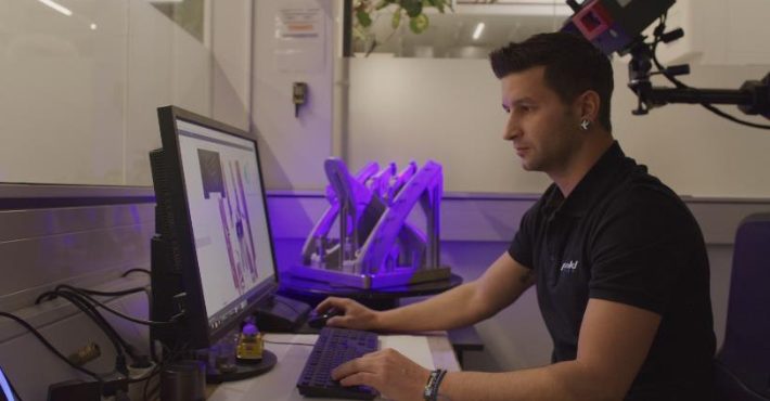
To check the geometrical accuracy of the parts, they are inspected via optical 3D-scanning, which can be seen as the standard method in additive manufacturing for this purpose. With a measurement accuracy in the μm-range, the 3D-scanning system gives profound information if the parts are within the given tolerance limits.
Before releasing the parts from the build platform, they undergo heat treatment, which is a stress relief annealing process to reduce the residual stresses inside the parts and their supports structure caused by the high thermal gradients during the printing process. This prevents from further distortion of the parts when releasing them from the build platform and removing the supports. Also, internal stresses are reduced to a minimum, which is crucial for the structural integrity of the parts.
The heat treatment is done in a full-automatic ALD Modultherm oven. During the heat treatment cycle the parts temperature goes up to more than 800°C in an inert Argon atmosphere.
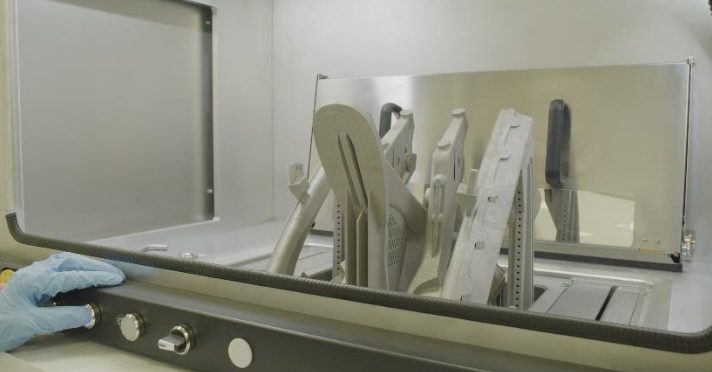
After heat treatment, the parts have to be separated from the build platform. In the case of the top frame, this is done with wire electrical discharge machining (EDM). This is just due to the fact that the parts are welded to the platform via the support structures. Then, all the still remaining support structures are removed.
After this, the printed raw parts are prepared for welding. Therefore, the functional surfaces are machined to achieve the requested tight tolerances which cannot be reached with just the pure printed surface.
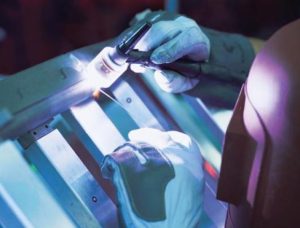
The Aeroscreen top frame is made out of a titanium alloy, which is a challenging material when it comes to welding. The responsible company Vsystem is an expert for such special requirements, on the Aeroscreen project they have developed specific welding parameters for the top frame to make sure it is in line with the quality requirements of RBAT and IndyCar. When the welding process is finished, the complete assembly gets a second heat treatment, again to reduce the residual stresses in the top frame which are introduced during the welding process and its thermal energy input which could again create distortions on the final component and further, to adjust the final material properties.
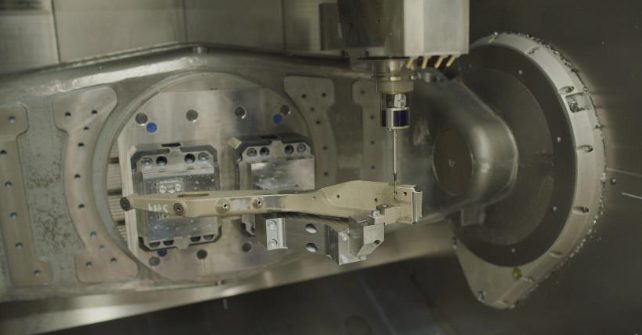
The final process step in the production of the top frame is the machining of the welded assembly and its functional surfaces. This is necessary to make sure that on the final assembly with its big dimensions, tight tolerances are achieved and the Aeroscreen fits perfectly to the IndyCar chassis and the windshield.
To ensure a good fit to the racing cars regarding the optical appearance, the Aeroscreen is then painted with a special paint in black.
After a final quality check, the part is put into a dedicated packaging, ready for shipment to the IndyCar facility where the top frame is assembled with the other components of the Aeroscreen and mounted on the chassis.
Once this is done the whole process is complete and the component is set for testing and competition.
Although designing and manufacturing the Aeroscreen was a very complex and demanding process for all involved, the efforts already paid off as this invention has already helped to prevent drivers from serious injuries and can be definitely seen as a success.
Find out more about Pankl Racing Systems at pankl.com.
Subscribe to our Newsletter
3DPresso is a weekly newsletter that links to the most exciting global stories from the 3D printing and additive manufacturing industry.