

Dimensional accuracy is one of the major concerns for Laser Powder Bed Fusion technologies since the process is characterized by high-temperature gradients, consolidation, and thermal expansion, which induce residual stress on the part. These stresses are released by separating the part from the baseplate, leading to plastic deformation. Thermo-mechanical finite elements (FE) simulation can be adopted to determine the effect of process parameters on final geometrical accuracy and minimize non-compliant parts.
In this research, a geometry for process parameter calibration is presented. The part has been manufactured and then analyzed with industrial Computed Tomography (iCT). A FE process simulation has been performed considering material removal during base plate separation, and the computed distortions have been compared with the results of the iCT, revealing good accordance between the final product and its digital twin.
The development of the regulation for additive manufacturing is crucial to determine the part quality, the machines and to define the application of such technology. Following the existing regulation norm ASTM/ISO 52902, the study presented proposed an artefact which includes many of the geometric details of the regulation and add some new features, all of them in one single manufactured object that is then measured through iCT and analyzed through a FE Analysis. Therefore, freeform shapes, lattice structures, and cavities have been produced to evaluate deformations and dimensional tolerances with a non-standard measurement method (iCT). The freeform shapes in this study are three 1.5 mm thickness metal sheets with different curvatures. There is also a horizontal freeform shape obtained below the flat surface of the plate. The material considered for the component production was an AlSi10Mg alloy powder 20–60 μm sourced from LPW Technology, Runcorn, UK, and printed with a layer thickness of 0.03 mm with one Yb (Ytterbium) fiber laser IR. The AlSi10Mg alloy has been chosen due to its popularity in the AM industry and the literature abundance of thermophysical properties data necessary for AM process simulation. The artifact has been manufactured with a Print Sharp 250 EP-M250 by Prima Additive, Torino, Italy with the coordination of SPEM srl.
During an iCT scan using an X-ray system, multiple projections are taken systematically. The images are acquired from several different viewing angles obtained with the rotation of the sample. It is possible to obtain radiographic imaging due to different X-ray attenuation coefficients of materials, and the X-ray linear attenuation coefficients are represented as different iCT grey values. In this research, the NSI X5000 TEC Eurolab system by North Star Imaging, Rogers, MN, USA, was used for the metrological analysis of the designed artifact.
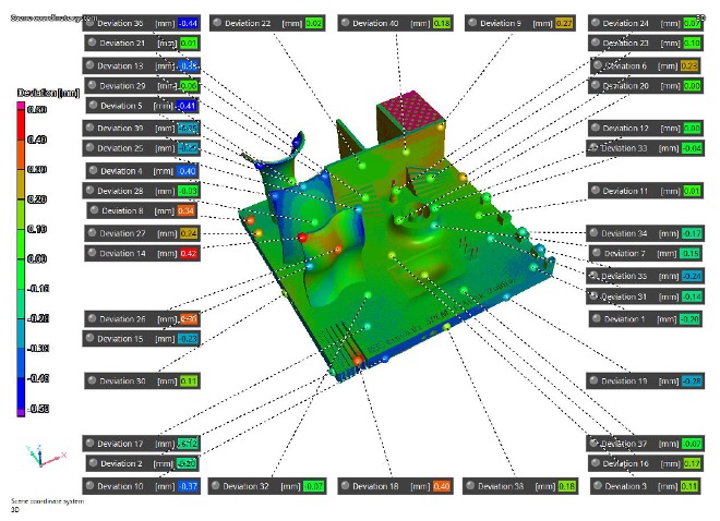

The simulation was done by using a software named AMTOP developed by ITACAe and Simtech which allow to determine the status of the stress, temperature and deformation layer by layer using a finite element method. The simulation was compared with the measured data obtained from iCT showing that some consideration had to be made when considering the cutting process. In facts in the second simulation considered the deletion of the elements of the plate and an extra 1.5 mm of the object as it was in the physical artefact. Such simulation gave good results compared with the measured data providing a good correlation with a value of 65% which is an encouraging result considering the complexity of the geometry. Thanks to the contribution of the software tool to the knowledge of the technology-based physical phenomenon, the implementation of the simulation methodology in the process engineering workflow can show several advantages to the manufacturer. These can be revealed in the reduction of time to market and costs, improvement of geometrical and structural properties, acceleration of the learning process, and the definition of a robust design methodology.
The activities presented in this article have been published in [1].
[1] Patuelli, C.; Cestino, E.; Frulla, G.; Valente, F.; Servetti, G.; Esposito, F.; Barbero, L. FEM Simulation of AlSi10Mg Artifact for Additive Manufacturing Process Calibration with Industrial Computed Tomography Validation. Materials 2023, 16, 4754. https://doi.org/10.3390/ma16134754
Website: https://www.mdpi.com/1996-1944/16/13/4754, PDF Version: https://www.mdpi.com/1996-1944/16/13/4754/pdf
Subscribe to our Newsletter
3DPResso is a weekly newsletter that links to the most exciting global stories from the 3D printing and additive manufacturing industry.