


F1 deals with similar issues described in this case study. Wiring in race cars is becoming more and more complex and Power Units are made up of several parts that need to be integrated into the final assembly. Available space is increasingly limited, so engineers are frequently utilizing flexible parts such as cooling ducts and wiring harnesses. The solution outlined here can be easily applied to the automotive racing world.
CRP Technology’s R&D department tackled the development of a new front air inlet for a Moto3 racing customer to solve space issues in the front fork area. It has been manufactured in WINDFORM® materials by using an SLS Additive Manufacturing technique.
Testing had shown that increasing air flow to the air-box improved the performance of the engine at every RPM range. This led the team as well as the engineers to conclude that they need to design a new track ready inlet. This design would make the air inlet longer, and bring the opening up to the front side of the fairing, in order to have a direct air flow with less turbulence.
Among the goals to be achieved, was the need to avoid modifying the existing frame and the existing triple clamps. The design would have to fit to the existing platform in order to test the on-track advantages and disadvantages of using this solution, and to make a direct comparison with the current standard inlet.
Additive Manufacturing (SLS) and WINDFORM® materials allowed for:
- Total freedom and no limitations in design (Design For Functionality instead of Design for Manufacturing)
- Creation of mock-up for assembling, fitting, and functionality
- Production of parts for performance tests
- Reduction in product and project realization timing
The final decision to use the new inlet came from its behavior on-track with the key points being it’s performance and reliability. Engineers kept the current airbox with the aim to mount the traditional air inlet as well as the new one and to acquire data of the airbox pressure on track.
The Project
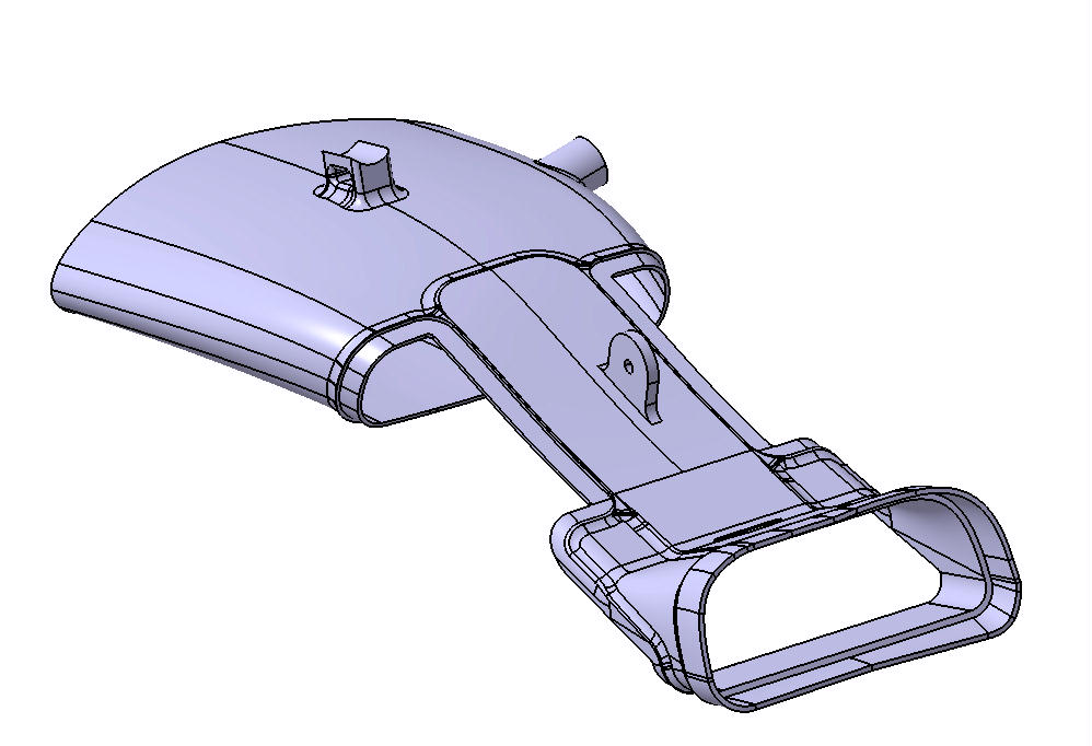
Through the use of Reverse Engineering, the original airbox was scanned and virtually assembled with the CAD system.
This allowed the engineers to be able to create a new model of the air inlet by taking into account the amount of available space, and the constraints of the assembly of the current airbox and frame.
First Prototype
Once a first draft of the air inlet was developed, a prototype in WINDFORM GF 2.0 was created. The decision to use WINDFORM® GF 2.0 was made to reduce costs, while being able to perform multiple tests with multiple prototypes.
The first prototype allowed engineers to see if the design fitment was correct and suitable for assembly. It was revealed by the first design that some sections needed to be changed due to the lack of space available under the lower triple clamp. This problem is further complicated when the bike is cornering and under braking conditions.
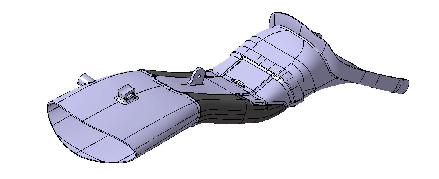
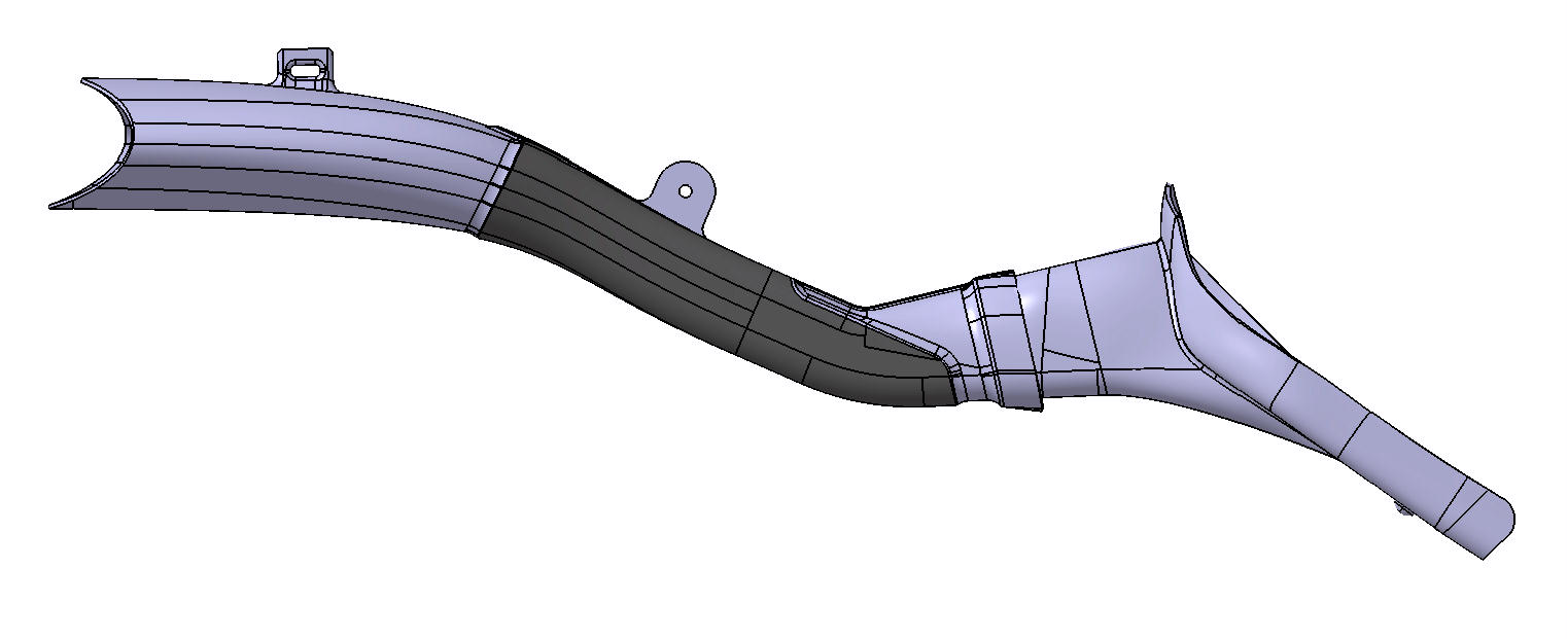
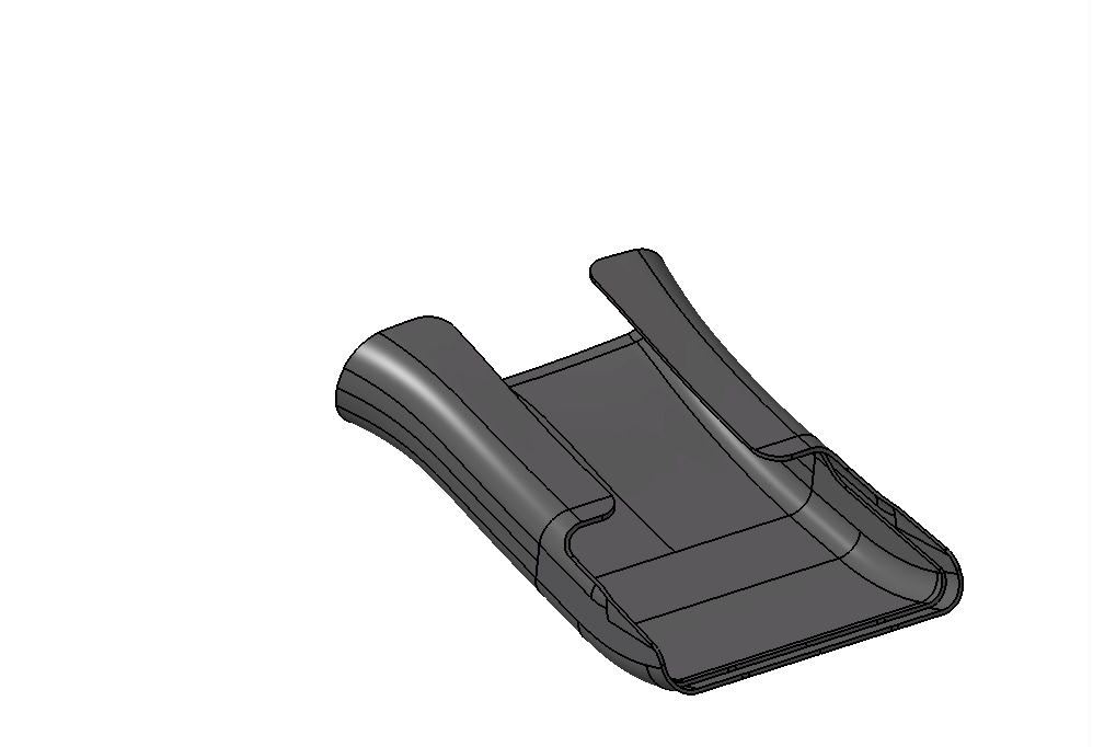
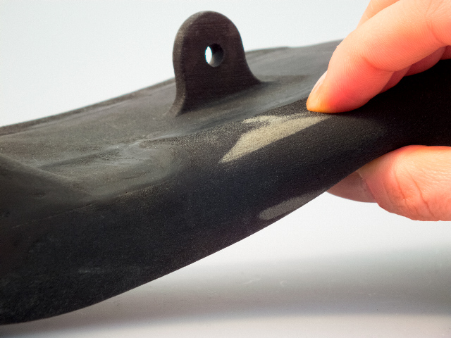
To optimize the volume of the inlet duct under the lower triple clamp, the engineers adopted a creative approach and decided to use a portion of the duct in WINDFORM® RL, the new rubber-like composite material produced by CRP Technology. This would be bonded to the main structure that was made out of WINDFORM® XT 2.0 for evaluation in racing conditions. To facilitate this they also carried out a bonding test to study the characteristics of the final assembly.
The concept was to make the bottom part of the duct with WINDFORM® RL in the fork and triple clamp area, and then assemble this into the top part produced in WINDFORM® XT 2.0. This approach would allow good clear airflow on the straightaway sections of the course, and thus an excellent flow to the airbox. Under breaking, the front fender could move up and collapse the inlet duct without any damages, due to the flexible material.
In addition, it was decided after examining the part that making the ducting flexible in the same area next to the front forks would off an additional benefit. The engineers were able to maximize the duct volume because the maximum steering actions are only reached when the bike is pushed into the paddock by the technical staff. In this situation, the front fork can tough the inlet duct deforming it without any damages.
Second Prototype
A second prototype was made in WINDFORM® GF 2.0.
Once the second prototype was mounded the engineers noticed some changes to be made, especially in the front fork area.
The soft section was too short and the forks could touch the area of the duct near the bonding overlap when steering travel was checked from lock to lock position. It was also seen that toward the back of the flexible area, near the airbox, that the duct was very close to the front wheel in the maximum braking position.
During testing it was determined that when the motorcycle was under severe braking, the front fender contact area on the duct in the soft part was too large. This situation, from the rider’s point of view, was not good because during hard braking, the steering must be free from movements, as the rider might need to correct the trajectory quickly.
The amount of input from the rider may be small, but it must occur very smoothly and too much contact of the front wheel assembly gave the impression of drag on steering. This affected the way the rider felt on the bike.
The team and engineers decided to change the inlet by reducing the portion that would make contact with the fender to reduce drag perceived by the rider.
The part made in WINDFORM® RL was enlarged according to the second test, and engineers and the rest of the team could get the correct fit for performance.
In the final test version, WINDFORM® XT 2.0 was utilized in order to reduce the weight of the front and central part of the inlet, while the WINDFORM® RL material was used for the flexible part of the inlet. The two parts were bonded together after being produced.
Bonding
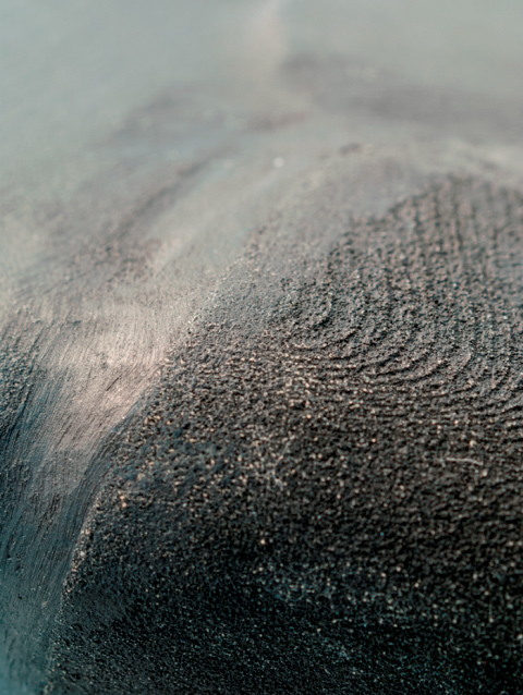
Bonding SLS parts is very important for the final result of the prototype: the right selection of bonding methods and adhesives will influence accuracy and functionality.
Subscribe to our Newsletter
3DPResso is a weekly newsletter that links to the most exciting global stories from the 3D printing and additive manufacturing industry.